I have started this project in 2015. Finally, after some modifications, I decided to publish it.
Yaesu 757GX2 is a quite old transceiver. Any repleacements parts are out of stock, no longer manufactured.
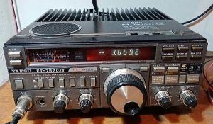
I have purchased the transceiver with broken VFD display and decided to build the display on my own. It wasn’t simple job to do. In the very beginning, I made a decision of fit the LED segment display in the trx instead of broken one. Although, I gave up with this idea.
I found some solutions for similar problem in the net, but neither of them seems to solve my problem: broken VFD, but the processor (TMS2370) was fine.
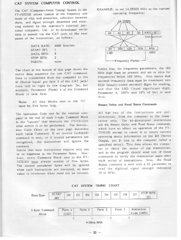
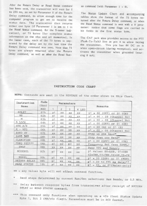
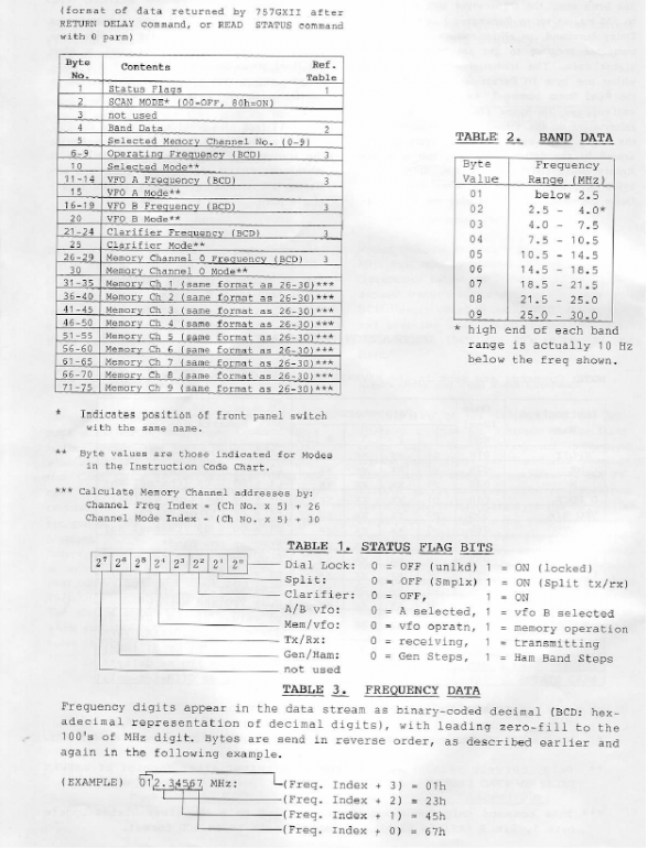
Based on 757’s user manual, espacially the CAT description interface, I decided to build the interface based on my favourite programmable platform – Arduino, to read the TRX status and show it on the external display.
Before I’ve started my fight with 757GX2 CAT interface, I found the James’es (VE3BUX) site with the library of FT-857D dedicated for Arduino to use with CAT interface. Unfortunatelly, this radio has a completely different protocol structure. What is more the software serial library had to be modified additionaly.
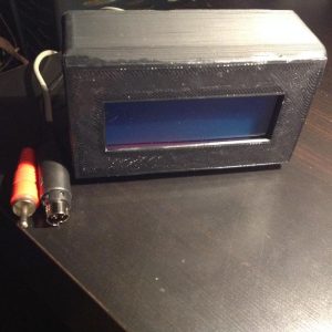
I used 4×20 LCD display. The connector used for CAT interface in 757GX2 is a mini-DIN 6PIN. Be careful, becouse I purchased two types of 6PIN mini-DIN ! The difference based on the connector’s shape. The 6PIN mini DIN purchased at TME (this one) doesn’t fit. The 6PIN mini-DIN SVHS did the job (this one). This is the same connector like the PS/2 keyboard. The power supply(8 or 12V) is taken by RCA connector from TRX.
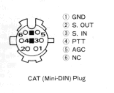
CAT socket.
S.OUT -> RX_YAESU, S.IN -> TX_YAESU
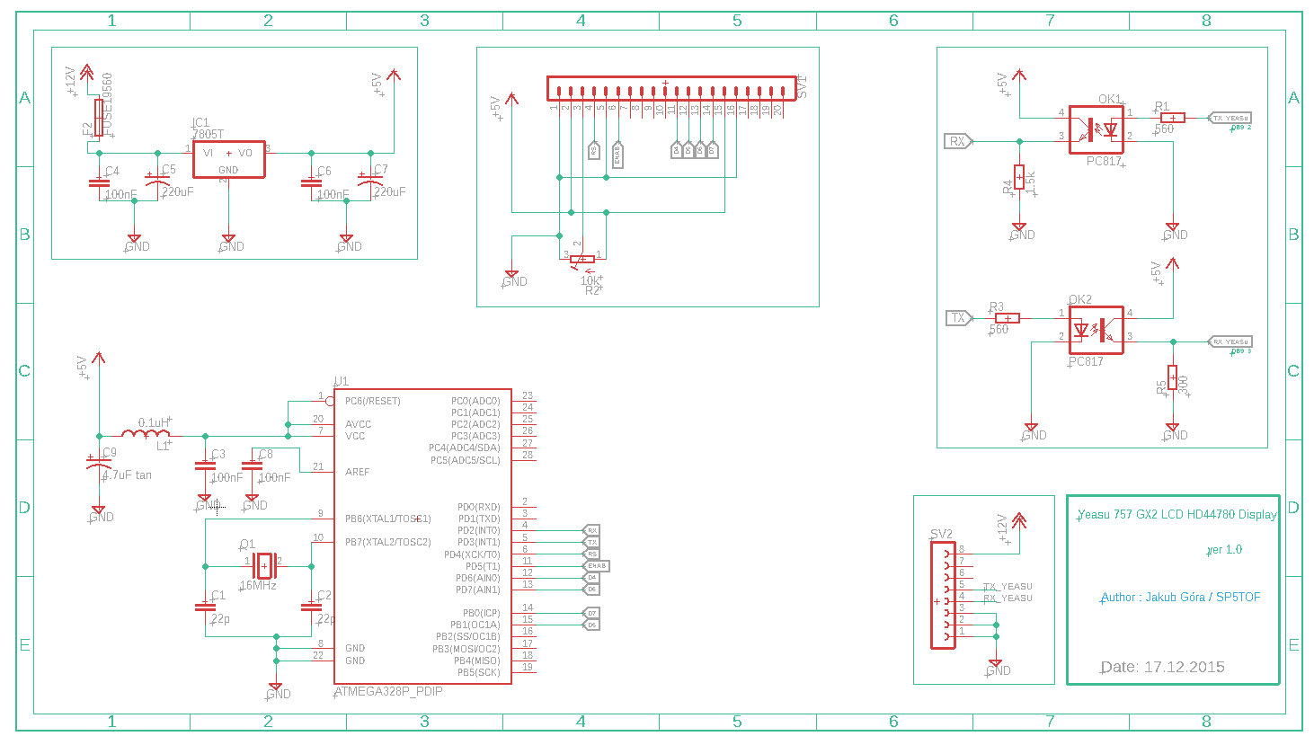
In the very beginning I was struggling with operate at high power. The LCD display have been showing mess when I had increased power to 50W-100W. I was fighting with it for many weeks and finally found a solution. I used the inductance and tantal capacitor within the power line of uC fo filter undemanded intereferences.
The whole device is opto-isolated from TRX by using the optocouplers on TX and RX line. The 757GX2 CAT interface is used a TTL logic level .
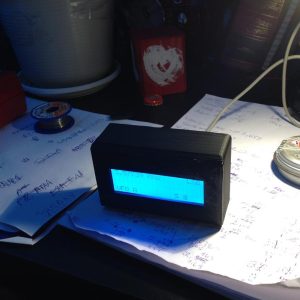
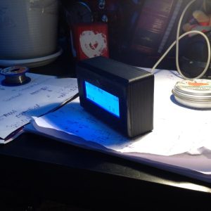
Please see this device in action:
Eagle Schema and PCB, arduino code & HEX file for Atmega328p, 3D case in STL format can be downloaded here
Please note that Software Serial Arduino’s library has to be swapped within Arduino IDE before programming the uC. I had to modify it becouse the data structure comes from 757GX2 has different sequence than genuine arduino library has.
JAKUB/SP5TOF