Intention for build an video splitter was followed by personal needs of switching between 4 CCTV cameras with infra-red remote controller and be possible to watching it with home TV.
I was inspired by project found on the internet, but currently I can’t provide a link.
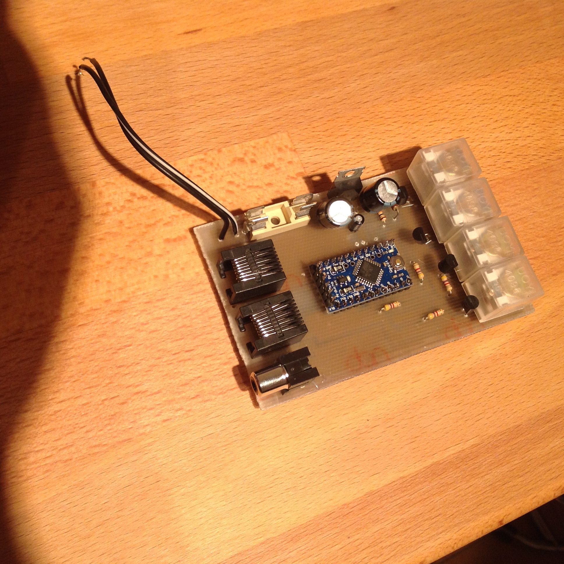
I used arduino controller & IR-code reader with relays driver.
Please find a schema:
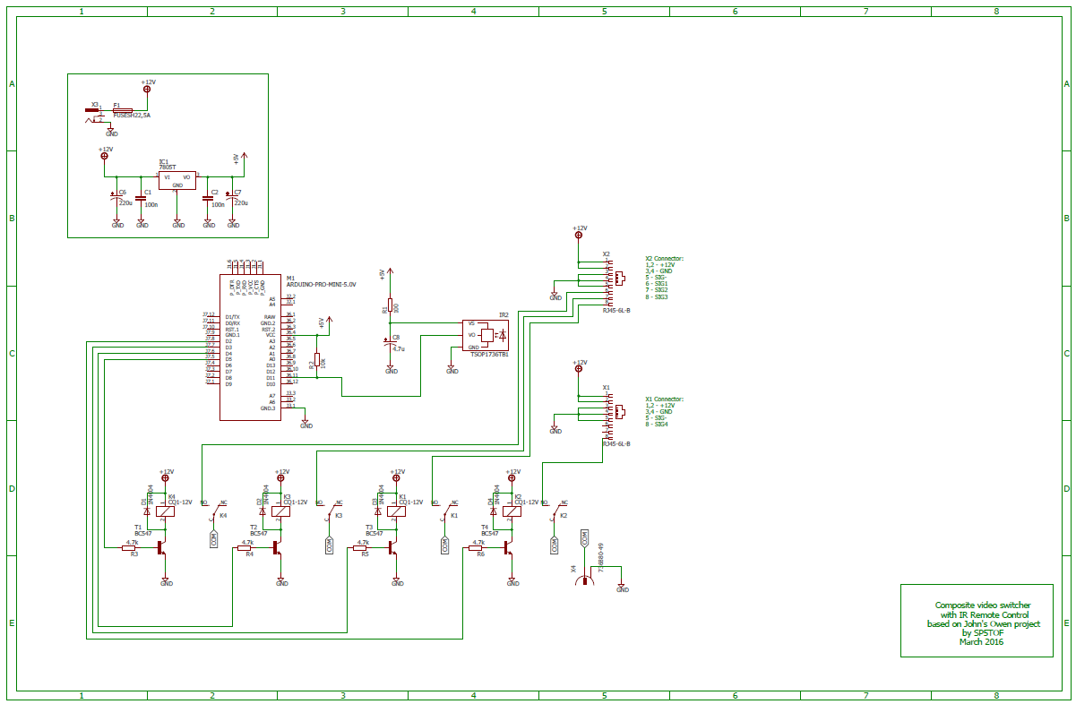
The IR sensor used in this project was TSOP, compatible with any TV IR remote controller.
You can connect up to 4 CCTV cameras to this device. If you press one from among 4 buttons of your remote controler, you will get an image of one CCTV camera on your TV . Composite video-in socket on your TV is used in this case.
Attached arduino code is prepared to support four collored buttons of Samsung-TV remote controller (intended for tele-text functionality). You can use any other buttons, but you’ll need to read out its IR-code and put into the arduino code.
I strongly recommend to use as short line of CCTV cable between camera and this device as possible (up to 5-6 meters). Longer line could cause quality problems of video. Line impendance matching is not solved enough in this project and need to be improved if you’re planning to use it with long distances between cameras and the switching device.
Power supply should must handle 4 cameras and switching device.
Attached schema is splitted into two parts: voltage stabilizer and switching part with uC. You can find two RJ45 sockets (called X1 and X2). Pins 1 ,2 and 3,4 with both sockets are intended for power the cameras and connected to main 12V power supply.
Three cameras are connected to X1 socket, one camera is connected to X2 socket. This is becouse one RJ45 socket is too small to support all cameras.
X4 socket is a simple RCA socket and used as an output of the composite signal and needs to be connected with video composite-in socket of TV.
Please find arduino code, eagle schema and PCB: Video Splitter
Jakub/SP5TOF